
CONTACT
Welcome to consult Providing quality services Tel(whats app):008618747138212 E-mail:bashiker@hotmail.com Wechat:tianshuai91
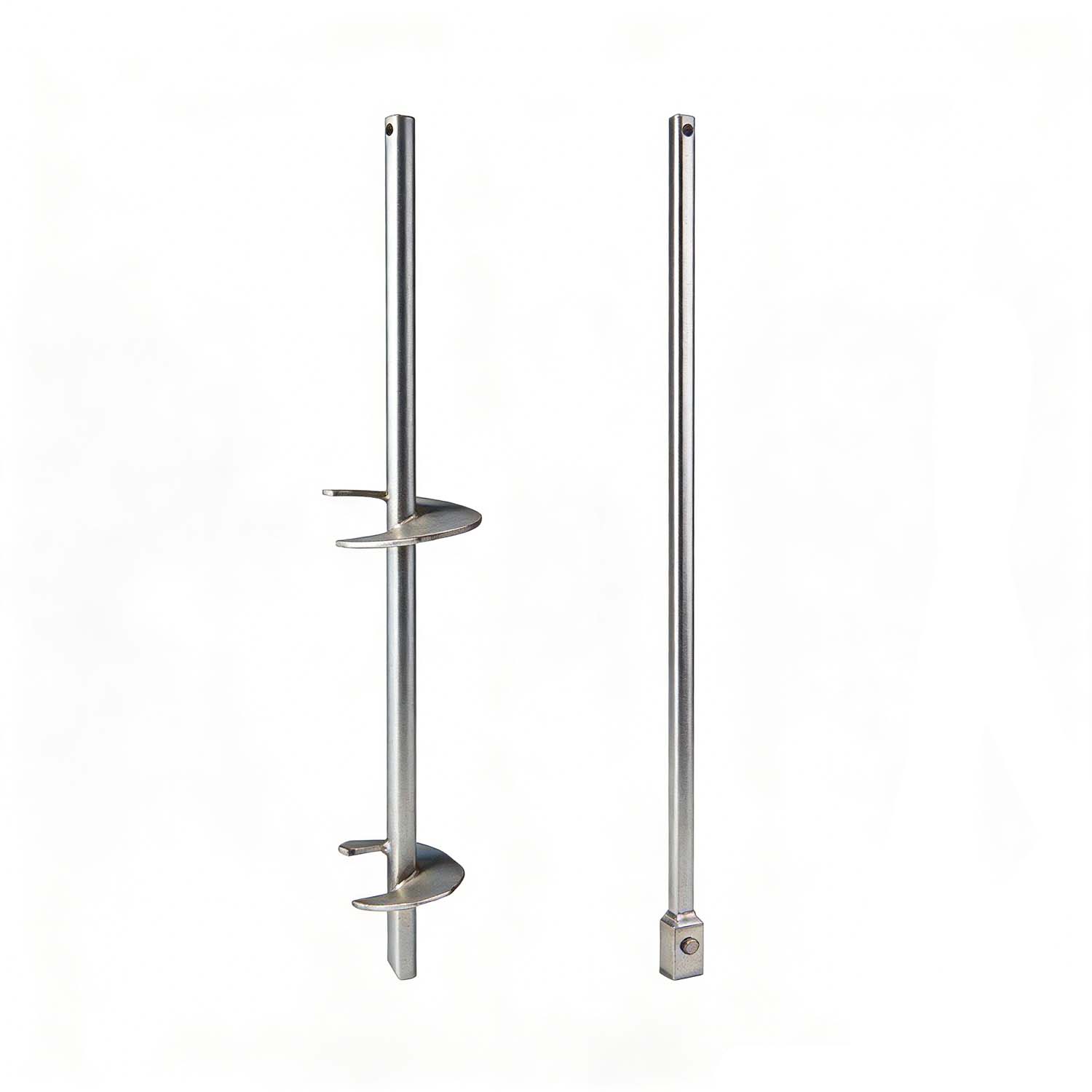
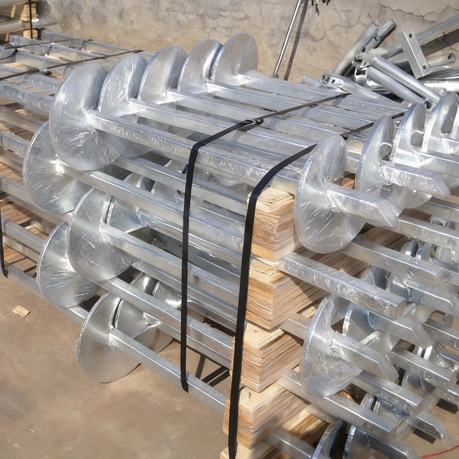
More contactsThe Grouted Helical Micropile does not require removing spoils from the site. By combining both end-bearing on the helical plates and skin friction along the rough surface of the grout column, the result is a higher-capacity pile system.
Speed: 40–50 piles per day/per crew
High capacity
Predictable results
Cost-effective
Labor-saving: smaller crews
No pre-drilling
Resistance to buckling in weak soils
Stiffer pile (deflects less at a particular load)
Additional corrosion resistance in aggressive soils
Deep Foundation Applications
Commercial/industrial
High capacity/greater than 100 tons
Underpinning applications
New construction
Build on weak soil sites
Limited access
Bridges
Grouted Helical Micropile Installation
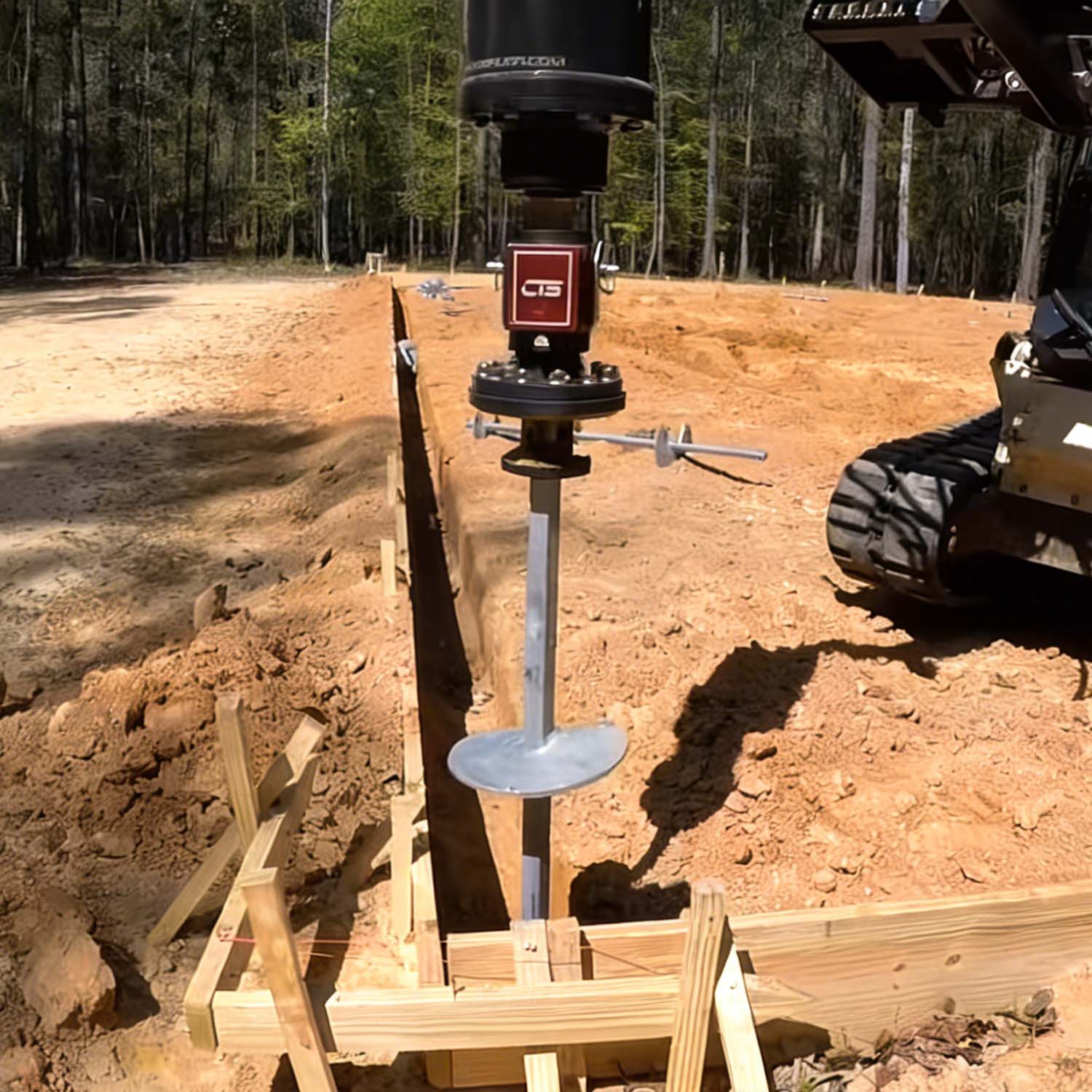
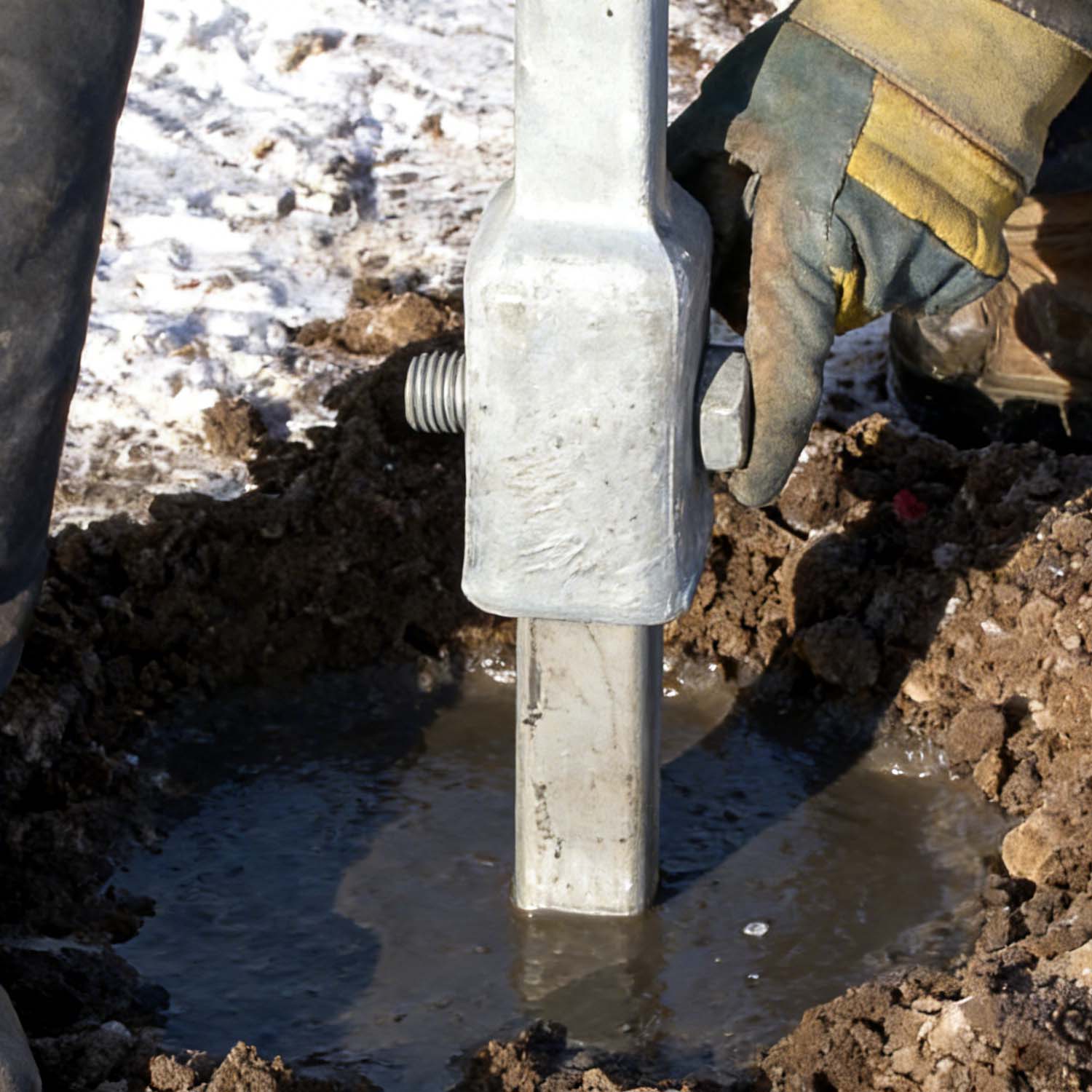
The Grouted Helical Micropile Systems are used to form a grout column around the shaft of a standard helical anchor/pile. The installation process can employ grout only or grout in combination with either steel or PVC casing. To start, a helical anchor/pile drives into the soil by applying torque to the shaft. The helical bearing plates require significant force or torque to advance the helical pile into the soil.
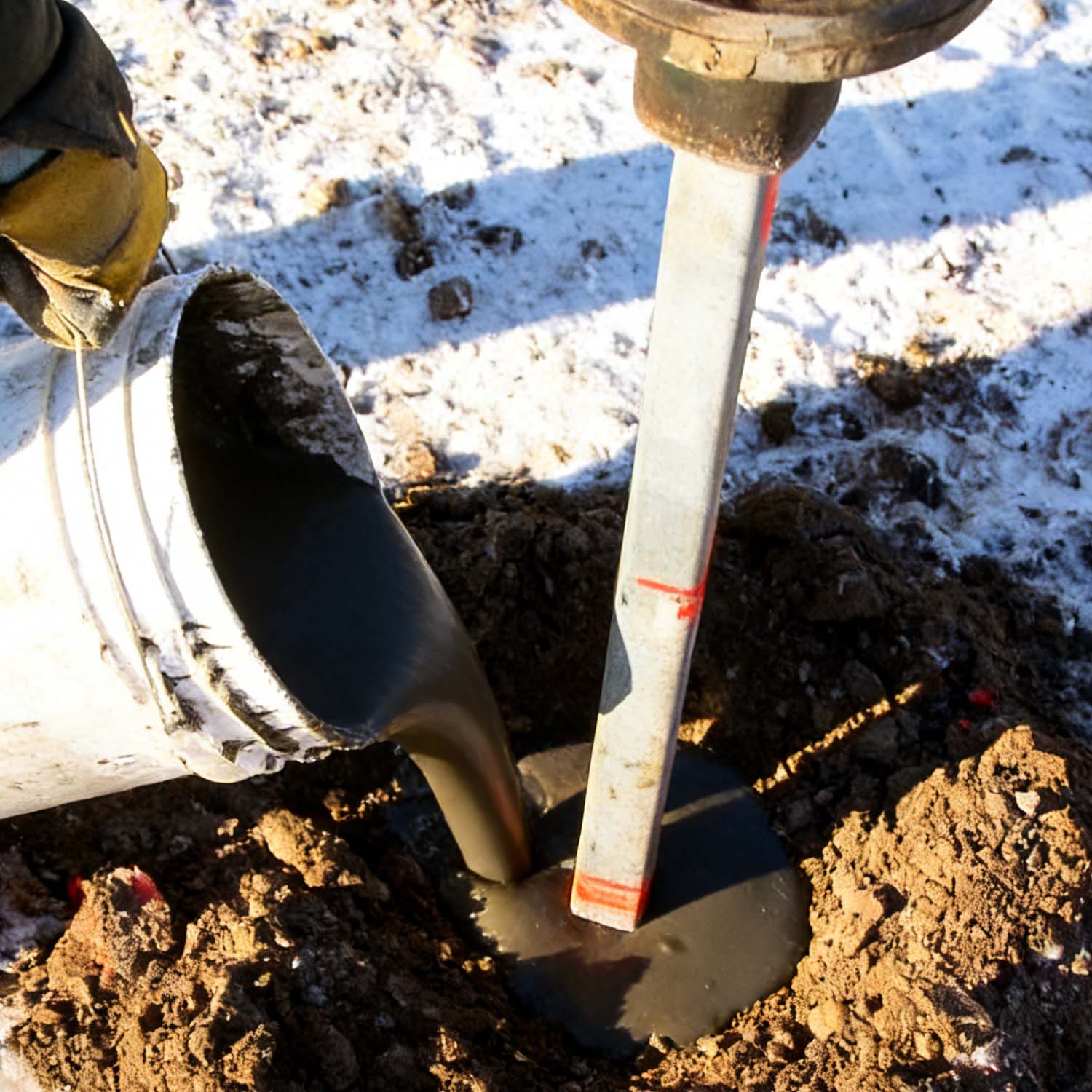
From a reservoir at the surface, a flowable grout immediately fills this void surrounding the shaft. Additional extensions and displacement plates are added until the helical bearing plates reach the minimum depth required or competent load-bearing soil. This displacement pile system does not require removing spoils from the site.
Specification:
|
Component
|
Material Grade
|
Dimensional Tolerance
|
Surface Treatment
|
Mechanical Properties
|
|
Main Shaft
|
ASTM A36 / ASTM A106 Grade B / Q235B
|
Diameter: ±0.5mm; Length: ±10mm
|
Hot-dip galvanizing (≥85μm zinc layer) / Epoxy coating (≥300μm)
|
Yield strength ≥240MPa; Tensile strength ≥400MPa; Elongation ≥20%
|
|
Helical Plates
|
ASTM A36 / Q355B
|
Thickness: ±0.3mm; Diameter: ±1mm; Pitch: ±2mm
|
Same as main shaft
|
Yield strength ≥240MPa (A36) / ≥355MPa (Q355B); Brinell hardness ≥120HB
|
|
Couplings (for extended shafts)
|
ASTM A105
|
Thread tolerance: 6g/6H
|
Hot-dip galvanizing
|
Tensile strength ≥485MPa; Yield strength ≥250MPa
|
|
Applicable Scope: Grouted helical micropiles for foundation support in civil engineering, geotechnical engineering, construction of industrial/commercial buildings, residential buildings, slope stabilization, and foundation reinforcement of existing structures
|
||||
|
Dimensional Specifications
|
||||||
|
Pile Model
|
Main Shaft Diameter (D)
|
Helical Plate Diameter (d)
|
Plate Thickness (t)
|
Plate Pitch (p)
|
Standard Shaft Length
|
Max Grout Column Diameter
|
|
BA-GHP-001
|
76mm (3")
|
200mm / 250mm / 300mm
|
8mm / 10mm
|
150mm / 200mm
|
3m-6m
|
150mm-200mm
|
|
BA-GHP-002
|
89mm (3.5")
|
250mm / 300mm / 350mm
|
10mm / 12mm
|
200mm / 250mm
|
3m-8m
|
200mm-250mm
|
|
BA-GHP-003
|
108mm (4.25")
|
300mm / 350mm / 400mm
|
12mm / 14mm
|
250mm / 300mm
|
4m-10m
|
250mm-300mm
|
|
BA-GHP-004
|
114mm (4.5")
|
350mm / 400mm / 450mm
|
14mm / 16mm
|
300mm / 350mm
|
4m-12m
|
300mm-350mm
|
|
BA-GHP-005
|
140mm (5.5")
|
400mm / 450mm / 500mm
|
16mm / 18mm
|
350mm / 400mm
|
5m-15m
|
350mm-400mm
|