
CONTACT
Welcome to consult Providing quality services Tel(whats app):008618747138212 E-mail:bashiker@hotmail.com Wechat:tianshuai91
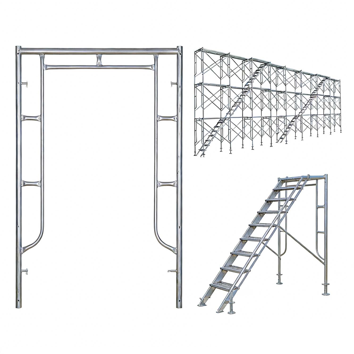
More contactsWork-through Scaffold Frame Applications
These frames excel in high-traffic or access-critical projects:
Masonry & Bricklaying Designed for the masonry industry, allows long, continuous platforms along walls while workers move freely below carrying bricks, blocks, or tools.
Stucco & Plastering provides easy passage for mixing equipment, hoses, or wheelbarrows; supports exterior finishing work on residential/commercial buildings.
Sidewalk Protection & Pedestrian Canopies (Sidewalk Sheds) Widely used in urban areas (e.g., New York City) to create overhead protection; frames support plywood/debris netting while allowing safe pedestrian passage below. Often paired with bridge legs for extended spans.
Building Maintenance & Renovation: Exterior repairs, painting, window installation, or facade work; enable movement along building perimeters without obstructions.
General Construction & Access Residential, commercial, and industrial sites for concrete pouring, cladding, or equipment maintenance; supports slab formwork or shoring in some configurations.
Key Benefits Driving These Applications
Unobstructed Access — Workers up to ~6' tall can pass underneath without ducking.
Material Flow — Easy transport of wheelbarrows, carts, or long materials.
Safety & Efficiency — Reduces tripping hazards; OSHA-compliant when properly assembled.
Versatility — Stacks with standard frames for multi-level platforms.
|
Comparison to Mason Frames
|
||
|
Feature
|
Mason (Step/Ladder) Frames
|
Walk-Through Frames
|
|
Design
|
Built-in rungs for climbing and plank support
|
Open arch (no mid-rungs) for full passage
|
|
Best For
|
Mid-level workbench needs; heavy material staging
|
Easy movement of wheelbarrows, long runs, pedestrian access under scaffold
|
|
Obstructions
|
Some at mid-height (rungs)
|
Minimal; clear walkthrough up to ~6' tall
|
|
Common Use
|
Pure masonry (brick/stucco close to wall)
|
Masonry + material transport; sidewalk sheds
|
|
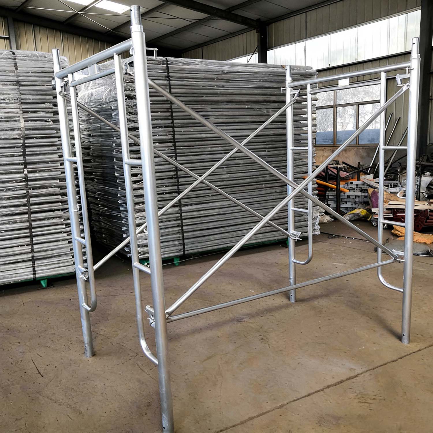
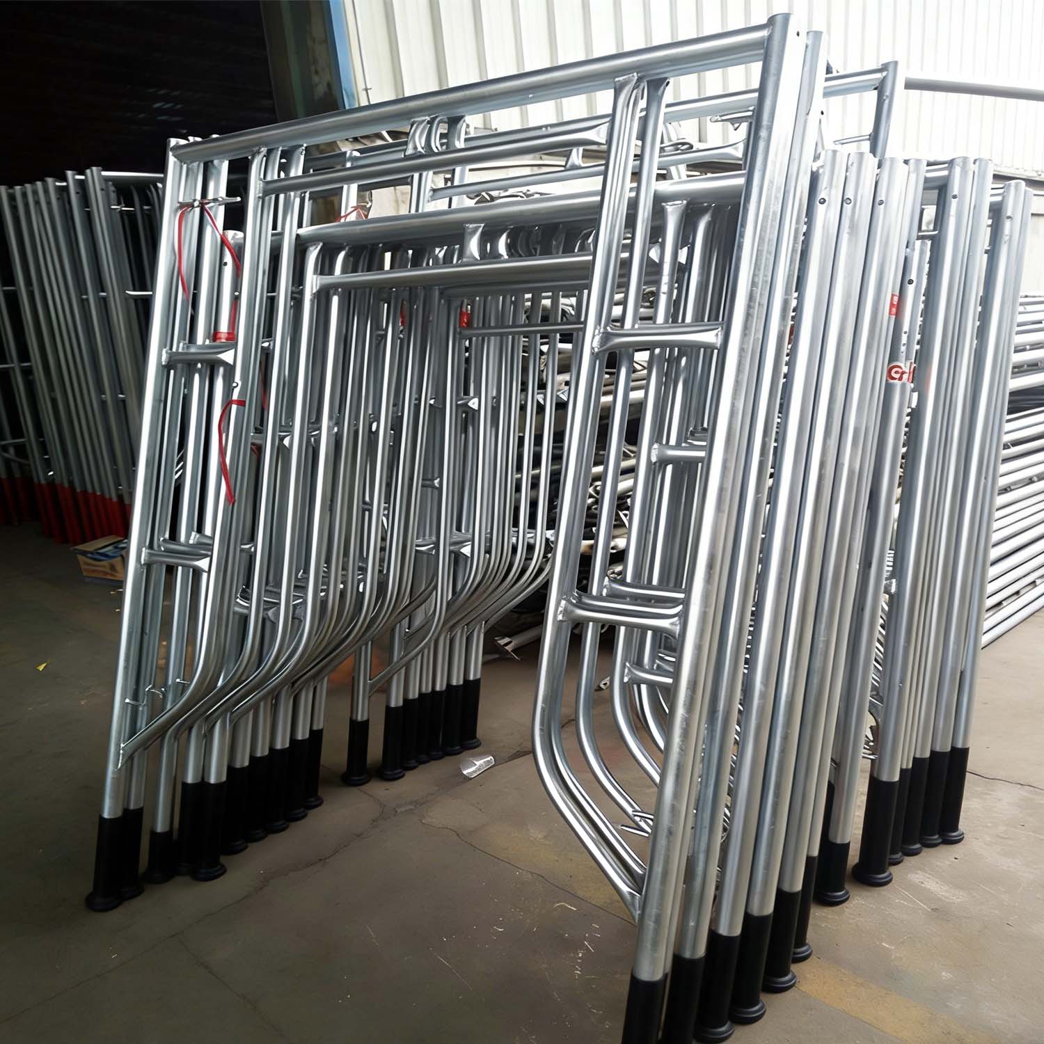
Specifications of Mason Scaffold Frame (Masonry Walk-Through Scaffold)
The following specifications are commonly used standard models for foreign trade export, complying with internationally universal dimensions (suitable for European, American, Southeast Asian, and other markets). Covering core parameters such as size, material, load capacity, and process, they can be directly used in product manuals, quotations, or purchase contracts: |
||
|
I. Core Dimension Parameters (Unit: mm)
|
||
|
Category
|
Exact Technical Specifications
|
Test/Executive Standards
|
|
Main Structure Dimensions (mm)
|
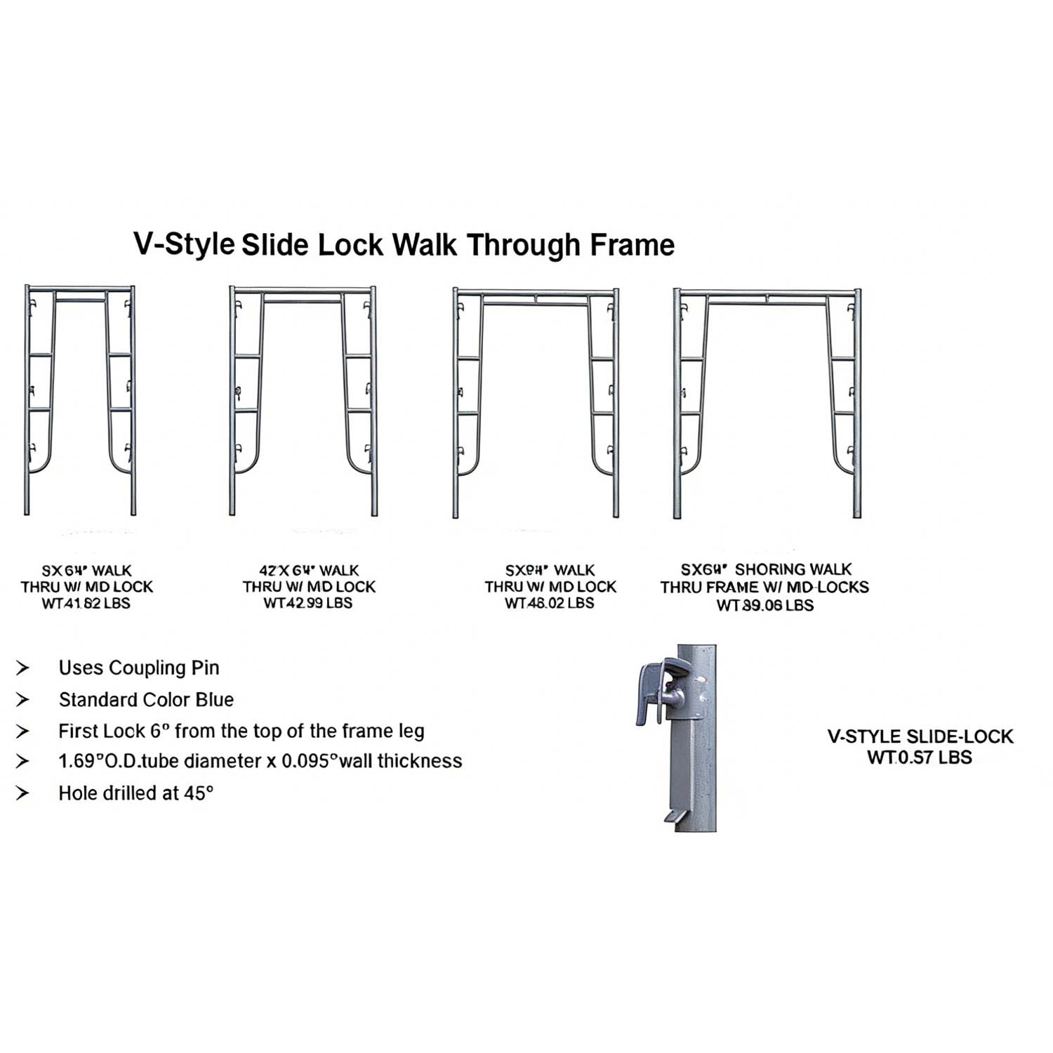
Frame Width: 914±1mm / 1219±1mm (Optional)
Frame Height: 1700±1mm / 1930±1mm / 2000±1mm (Optional) Vertical Tube Diameter: 42×2.5±0.1mm / 48×2.75±0.1mm Crossbar Spacing: 900±2mm / 1000±2mm Vertical Tube Center Distance: 914mm / 1219mm (Consistent with width, tolerance ±0.5mm) |
GB/T 19154-2017 Clause 5.2
EN 12811-1:2003 Clause 6.3 |
|
Material Standards
|
Main Frame: Q235B Low-Carbon Steel (C content 0.12%-0.20%, Mn content 0.30%-0.65%)
Heavy-Duty Main Frame: Q355B High-Strength Steel (Yield Strength ≥355MPa) Cross Bracing: Q235A Steel (Tensile Strength ≥370MPa) Connecting Rod: 45# Steel (Quenched and Tempered, Hardness HB200-230) |
GB/T 700-2006
ASTM A36/A36M-20 EN 10025-2:2004 |
|
Surface Treatment
|
Hot-Dip Galvanizing: Coating Thickness ≥85μm (Minimum Local Thickness ≥70μm), Salt Spray Test (ASTM B117) ≥72 Hours Without Red Rust
Electro-Galvanizing (Economical Model): Coating Thickness ≥20μm, Salt Spray Test ≥24 Hours Without Rust Welding Process: Automatic CO Gas Shielded Welding, Weld Height ≥4.0mm, Weld Inspection Conforming to GB/T 11345-2013 Class |
ASTM B117
GB/T 11345-2013 EN ISO 15614-1:2017 |
|
Load Capacity (Exact Test Values)
|
Rated Static Load: 25kN/(Uniform Load, Test Standard GB/T 19154-2017 Clause 6.5)
Single Vertical Tube Axial Load-Bearing Capacity: 18kN (Ultimate Load ≥36kN) Lateral Displacement Resistance: ≤L/600 (L = Scaffold Span, Tested Under Horizontal Load of 1kN) Wind Resistance Grade: ≥Grade 10 (No Permanent Deformation at Wind Speed of 25m/s |
GB/T 19154-2017 Clauses 6.5-6.7
ANSI A10.8-2011 Clause 5.3 |
|
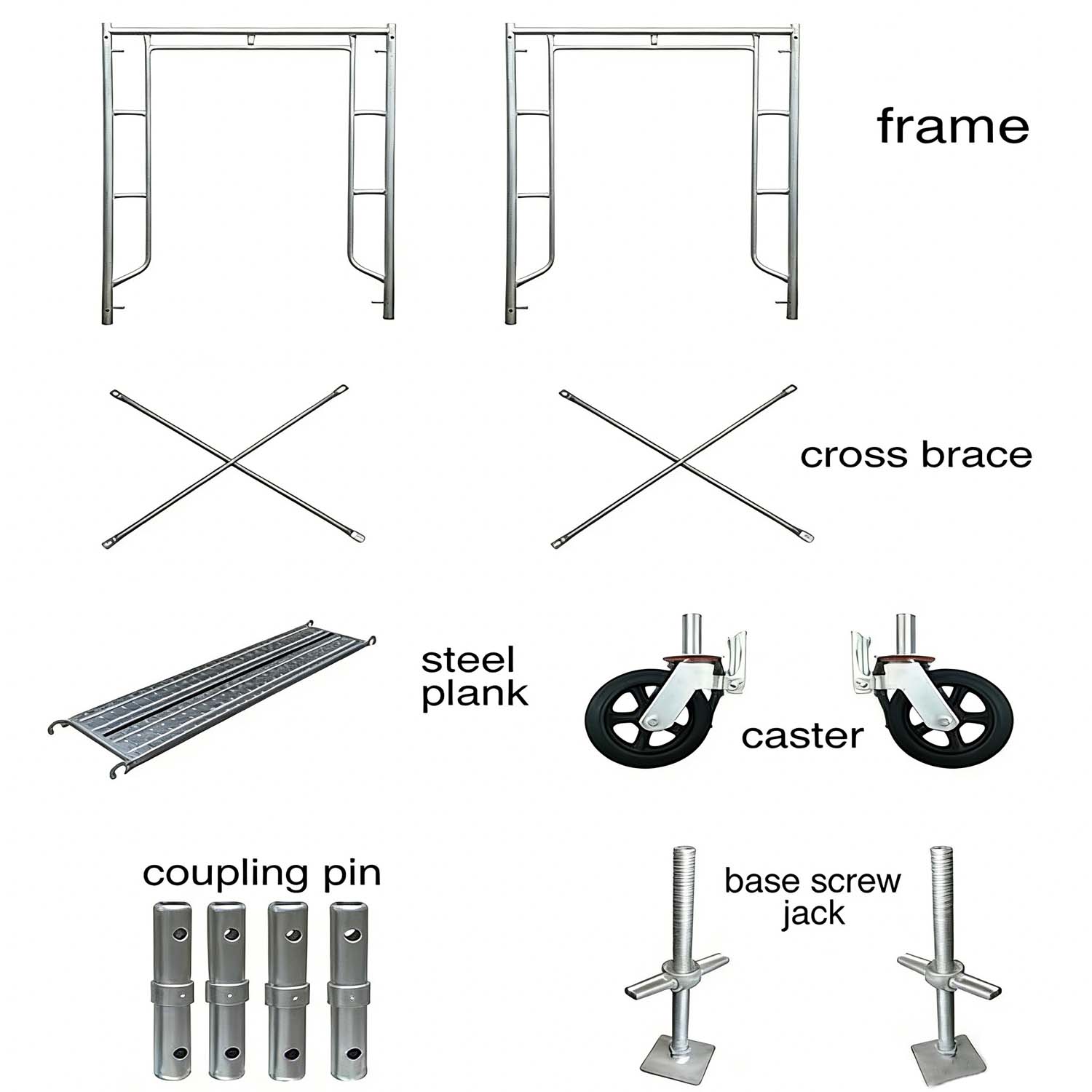
Exact Specifications of Core Accessories
|
Cross Bracing: Length 1700±2mm / 1930±2mm, Tube Diameter 25×2.0±0.05mm, Tensile Strength ≥350MPa
Adjustable Base Jack: Adjustment Range 0~150mm, Base Plate 150×150×8±0.2mm (Q235 Steel Plate Stamping), Load-Bearing ≥30kN Connecting Rod: Diameter 16±0.1mm, Length 160±1mm, Surface Carburizing Treatment (Hardness HRC40-45) |
GB/T 19154-2017 Appendix A
EN 12811-2:2003 |
|
Executive Standards (Exact Clauses)
|
China: GB 19154-2017 Chapters 5-7 (Dimensional Deviation, Material Requirements, Load Testing)
EU: EN 12811-1:2003 Clauses 5-8 (Including Essential Parameters for CE Certification) USA: ANSI A10.8-2011 5.1-5.6 (Load Safety Factor ≥2.5) Australia: AS/NZS 1576.3:2013 4.3 (Surface Treatment and Durability Requirements |
Citation of Corresponding Standard Clauses (Essential for Foreign Trade Compliance)
|
|
II. Accessory Specifications
|
||
|
Accessory Name
|
Exact Technical Specifications
|
Test/Executive Standards
|
|
Cross Bracing
|
Material: Q235A Steel (Tensile Strength ≥370MPa, Yield Strength ≥235MPa)
Dimensions: Length 1700±2mm / 1930±2mm (matching corresponding frame height), Tube Diameter 25×2.0±0.05mm, Vertical Tube Spacing 914/1219mm (matching frame width) Process: Overall hot-dip galvanizing (Coating Thickness ≥80μm, Salt Spray Test ASTM B117 ≥48 Hours Without Rust), Stamped end joints (Tolerance ±0.3mm) |
GB/T 19154-2017 Appendix A.2
EN 12811-2:2003 Clause 7.2 ANSI A10.8-2011 5.4 |
|
Connecting Rod
|
Material: 45# Steel (Quenched and Tempered, Hardness HB200-230, Carbon Content 0.42%-0.50%)
Dimensions: Diameter 16±0.1mm, Length 160±1mm, Thread Specification M16×1.5 (Tolerance ±0.05mm) Process: Surface Carburizing Treatment (Carburized Layer Thickness 0.8-1.2mm), Anti-Rust Grease Coating (Compliant with GB/T 4879-2016) |
GB/T 19154-2017 5.6
EN ISO 898-1:2014 ASTM A325-2017 |
|
Adjustable Base Jack
|
Material: Base Plate Q235B (Thickness 8±0.2mm, Size 150×150±1mm), Adjusting Screw 45# Steel (Diameter 36mm, Pitch 4mm)
Performance: Adjustment Range 0~150mm (Smooth Adjustment Without Jamming), Rated Load-Bearing Capacity ≥30kN (No Permanent Deformation Under Axial Pressure Test) Process: Stamped base plate, Hot-dip galvanized screw (Coating Thickness ≥70μm) |
GB/T 19154-2017 5.5
EN 12811-3:2004 AS/NZS 1576.3:2013 Clause 5.2 |
|
Safety Net
|
Material: High-Density Polyethylene (HDPE), Wire Diameter 2.0±0.05mm
Dimensions: Mesh Size 50×50±2mm, Net Sheet Specification 2000×1000mm/2440×1219mm (matching frame width) Performance: Tensile Strength ≥1.8kN/m, Elongation at Break ≤15%, Flame Retardant Grade V-2 (Compliant with UL94 Standard) |
GB 5725-2019
EN 1263-1:2019 ANSI A10.11-2014 |
|
Horizontal Frame
|
Material: Crossbar Q235A Steel (Tube Diameter 38×2.0±0.1mm), Bracket Q235B Steel
Dimensions: Width 914±1mm / 1219±1mm (matching frame width), Crossbar Spacing 500±2mm Process: Automatic CO Gas Shielded Welding, Weld Height ≥3.5mm, Weld Inspection Conforming to GB/T 11345-2013 Class II |
GB/T 19154-2017 5.4
EN 12811-1:2003 Clause 6.4 |