
METAL PROCESSING
CONTACT
Welcome to consult Providing quality services Tel(whats app):008618747138212 E-mail:bashiker@hotmail.com Wechat:tianshuai91
More contacts
Automatic Bending Center Working Process Description:
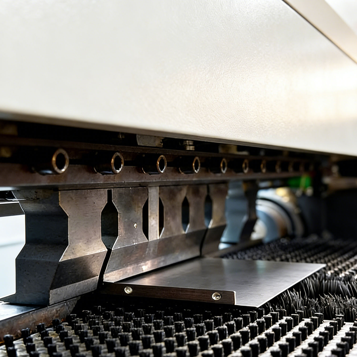
The automatic bending center is an intelligent and high-precision mechanical equipment widely used in metal processing, construction, and sheet metal manufacturing industries, mainly for continuous, automated bending forming of metal plates and profiles The detailed working process is as follows:
1 Equipment and Material Check
Inspect the overall status of the automatic bending center: check the normal operation of the hydraulic system, electrical control cabinet, servo drive, bending die, conveyor belt, and clamping mechanism; confirm the oil level of the hydraulic station, the tightness of the air pressure system, and the integrity of the die (no wear, deformation, or looseness).
2 Die Installation and Calibration
According to the bending shape, angle, and radius required by the workpiece drawing, select and install the matching upper die (punch) and lower die (die) on the bending slide and workbench of the center; use a special wrench to fix the die to prevent displacement during high-speed operation.
3 Numerical Control (NC) Parameter Input
Operate the human-machine interface (HMI/ touch screen) of the bending center, and input the processing parameters according to the design drawing of the finished product: including workpiece material type, thickness, bending angle (single/multiple angles), bending radius, bending position (coordinate points), number of bending passes, feeding speed, bending force, slide stroke, and pause time between processes.
4. Automatic Feeding & Positioning
Place the inspected metal workpieces on the automatic feeding rack/ conveyor belt of the bending center (the feeding rack is equipped with a material separation mechanism for bulk workpieces to avoid overlapping). For long profiles or large plates, the automatic feeding system with servo motor drive will realize unmanned continuous feeding; for small batch workpieces, manual auxiliary loading is optional.
The feeding system is equipped with a material detection sensor: when the sensor detects that the workpiece is in place, it sends a signal to the control system, and the subsequent process is automatically triggered.
Specification
|
Standard Sheet Specification & Blanking Size Nesting Arrangement
|
|
||
|
Sheet Thickness (t)
|
Common Standard Sizes (Length × Width, mm)
|
Applicable Process
|
Tolerance Value (per meter)
|
|
0.5~3mm
|
1220×2440, 1500×3000
|
Laser cutting
|
≤0.2mm
|
|
3~10mm
|
1500×3000, 2000×4000
|
Laser cutting
|
≤0.2mm
|
|
10~25mm
|
2000×4000, 2500×5000
|
Laser cutting
|
≤0.2mm
|
|
Neutral layer length = bending straight edge length + bending allowance (ΔL)
Batch production uses the empirical value table of bending allowance (for 90° bending, the most common) to simplify calculation: | Material | Thickness t (mm) | Bending Radius R=t | Bending Radius R=2t | Bending Radius R≥3t | |----------------|------------------|--------------------|--------------------|---------------------| | Carbon Steel | 0.5~3 | 0.1t | 0.2t | 0.3t | | Carbon Steel | 3~10 | 0.2t | 0.3t | 0.4t | | Stainless Steel| 0.5~3 | 0.2t | 0.3t | 0.4t | | Aluminum Alloy | 0.5~3 | 0.15t | 0.25t | 0.35t | |
|||
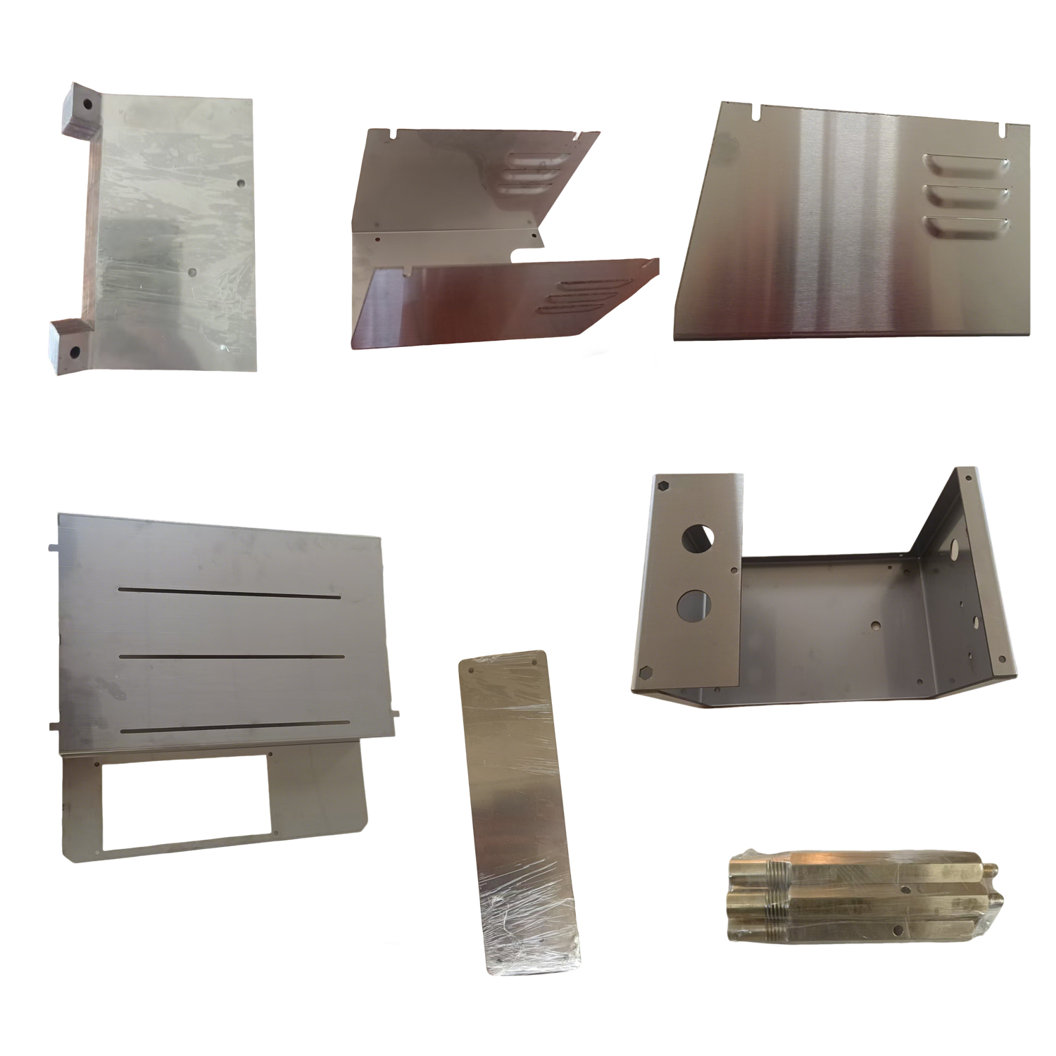
Accept customized types from different materials ( Steel, stainless steel,Aluminium ,Copper )